This article will cover the implementation of of a L3VPN between a Junos PE device and and a Cisco PE device. Basic high level knowledge of MPLS / BGP is assumed and the post will cover all the other aspects that are inherently associated with L3VPNs.
The following technologies will be covered in reasonable depth.
- IS-IS Underlay Routing
- BGP (VPNv4) Signalling
- BGP Route Reflection
- BGP Confederation
- MPLS LDP
- LDP Tunnelling
- MPLS RSVP-TE
- Basic Traffic Engineering
- VRFs & Routing Instances
- PE-CE Routing

Technology / Design Overview
There are a few components that will be configured throughout our topology – these are described briefly below, mainly in the context of our topology:
- Devices:
- Junos ‘P’ Devices
- vMX1 & vMX3
- IOS-XRv ‘P’ Device
- XRv1
- Junos ‘PE’ Devices
- vMX5 & vMX6
- IOS-XRv ‘PE’ Device
- XRv2
- Cisco CSR ‘CE’ Devices
- CPE101, CPE201 and CPE301
- CPE101, CPE201 and CPE301
- Junos ‘P’ Devices
- Underlay routing protocol – to provide reachability / transport to the loopback of other core devices and also the wider topology. This will be IS-IS
- IS-IS will be used to support a basic traffic engineering requirement – which will be covered later
- This will be ran in ‘Level 2’ mode on the P devices, with PE devices running L2 towards the core and L1 back in towards the POP.
- Edge (PE) devices Will run in both Level 1 / Level 2 mode; Level 2 towards the core and Level Intra-POP towards other local edge devices or similar.
- MPLS Transport / Labelling Protocols – to allocate and distribute label bindings for transport
- RSVP-TE (RFC 3209) will be used for transport of customer VPN traffic across the core;
- Allows for bandwidth reservation – which is what RSVP was originally designed for
- Allows for traffic engineering (such as explicit paths or backup paths) through extensions, note the ‘TE’
- LSPs (Label switched paths), which are unidirectional states, will be created in a full mesh manner between ‘XRv1’, ‘vMX1’ and ‘vMX3’ – which are P devices.
- Due to the soft state associated with a RSVP full mesh on larger SP networks, Segment routing (SPRING) may be used as a more recent alternative.
- Due to the soft state associated with a RSVP full mesh on larger SP networks, Segment routing (SPRING) may be used as a more recent alternative.
- LDP (RFC 5036) will be used between the ‘POPs’ PE devices and core MPLS ingress ‘P’ Devices
- Instead of running RSVP-TE to the PE devices themselves, only LDP will be ran since we would not benefit from TE on the single link between the devices. This is one way of reducing state on the PE devices
- Running LDP to the POP also allows for simpler provisioning and reduced state on edge devices. Put simply we won’t have to configure a potential full mesh of RSVP neighbours here, unlike the core.
- Whilst the above sounds good, services such as MPLS L3VPNs require end to end LDP label information, so we will be tunnelling LDP over RSVP-TE on the ‘P’ devices.
- Targeted (non directly connected) LDP sessions are formed between the ingress and egress routers of the RSVP LSP that you wish to tunnel LDP over.
- Transit P routers (MPLS label swapping only), will not be involved in the LDP label exchange
- This will result in the P devices essentially stitching LDP information from a PE over the core
- It allows LDP peers to make use of Traffic engineered RSVP-TE LSPs
- From the perspective of LDP device, such as a PE device, a RSVP LSP is seen as one hop metric wise
- The real traffic control and metrics are implied by the RSVP LSP that LDP traffic will be tunnelled over for a particular flow, more accurately a FEC in this case.
- Targeted (non directly connected) LDP sessions are formed between the ingress and egress routers of the RSVP LSP that you wish to tunnel LDP over.
- The inner workings of LDP will be explored in further depth during the verification phase.
- Instead of running RSVP-TE to the PE devices themselves, only LDP will be ran since we would not benefit from TE on the single link between the devices. This is one way of reducing state on the PE devices
- RSVP-TE (RFC 3209) will be used for transport of customer VPN traffic across the core;
- BGP Scaling Methods – whilst not strictly needed, we will be configuring both a BGP Confederation and also make use of Route Reflection as methods to work around the ‘full mesh’ requirement of iBGP
- Confederation (RFC 5065) – this will divide our ‘global’ AS (‘123’) up allowing ‘POPs’ to be divided into their own sub-AS each
- Each sub AS will form a special form of eBGP peering known as I(Intra-confederation) eBGP peer
- Attributes such as Local Preference, MED and Next Hops are retained, unlike true eBGP
- This allows greater control of routing policy between the sub AS’s
- Each sub AS can run its own IGP and act as a isolated island.
- We will run a common IGP throughout our topology for simplicity
- (I) eBGP policies can be configured as required
- The choice to use confederations in this case is more of a technical exercise
- Use of a confederation in reality would likely be considered if control of each sub-AS was to be delegated or similar.
- Each sub AS can run its own IGP and act as a isolated island.
- There are some caveats their use can bring:
- To ensure network wide loopback reachability, route leaking may be required if different IGPs in the sub AS’s were to be used.
- Inter AS configuration is required to share VPNv4 information over a eBGP peer.
- In our topology, this is done over the multihop (loopback) peerings from our P to PE devices in each POP
- Due to the above there is a additional command required on Cisco devices – this will be covered in the configuration
- AS65000 is our ‘core’ sub AS consisting purely of ‘P’ devices peering iBGP to a route reflector
- We have 3 ‘POPs,’ AS65101, AS65102 and AS65103. These POPs will run intra-confederation eBGP peerings back to AS65000.
- Our POPs only consist of PE devices for simplicity’s sake; to keep the number of devices in our topology down. A ‘real world’ design may or may not have P devices on the border, this would likely come down to whether transiting traffic through that POP was required as part of the wider network design / strategy.
- Route Reflection – this consists of using a central point or points that is / are aware of all the BGP routing information within the AS, this point would then ‘reflect’ information learnt from ‘clients’ to other ‘clients’ and ‘non-client’, with certain rules:
- (RR)s, reflect their best path to clients, similar to normal BGP operation.
- Non-Clients are devices that aren’t served as a ‘client’ by the RR in question, but have a iBGP full mesh to it and vice versa.
- Clients are devices that peer with a particular RR, on Cisco IOS, this needs explicitly configuring on the RR.
- Client peer learnt prefixes are reflected to all other client and non-client peers
- eBGP peer learnt prefixes are reflected to both clients and non-clients
- Non-Client learnt prefixes are only reflected to clients. Reflecting them to non-clients would result in the violation of a loop-prevention rule; ‘iBGP peers will not advertise a iBGP learnt prefix to another iBGP peer’
- Confederation (RFC 5065) – this will divide our ‘global’ AS (‘123’) up allowing ‘POPs’ to be divided into their own sub-AS each
- We will use ‘vMX3’ as the VPNv4 Route Reflector (RR) in our topology
- This will be in the forwarding path as this will just be a P device in the topology – We will preserve the BGP next hop as this will be a fundamental aspect of ensuring labels etc are generated correctly by MPLS devices.
- Route Reflectors can cause sub-optimal routing if not strategically placed. BGP features such as ‘add path’ can help address these shortcomings, but is not covered on this post.
- Overlay routing protocol – to signal ‘customer’ VPN information
- MP-BGP (VPNv4 sub-address family) will be made use of to signal customer VPN routes between the edge (PE) devices. This is a fundamental aspect of L3VPNs
- PEs take IPv4 routes they learn from customer VRFs and then advertise them as ‘VPNv4’ routes to other VPNv4 peers
- In our case, this will be the PEs advertising them via eBGP to our P devices, but usually this is PE to PE over iBGP peerings
- A RD (Route Distinguisher) is used to keep the routing tables unique on a PE
- A RD is prefixed to advertised VPNv4 routes
- A RD consists of 8 out of the 12 bytes of a VPNv4 update
- Type 0: 2 byte ASN : 4Byte Number.
- E.g. 65000:4123456789
- Type 1: 4 byte IP : 2 byte number
- E.g. 10.255.255.101:65536
- Type 2: 4 byte ASN : 2 byte number
- E.g. 4123456789:65536
- Type 0: 2 byte ASN : 4Byte Number.
- If the same RD is used for a particular VRF, but on different PEs, it could cause a loss of routing information; consider a Active / Active BGP scenario with route reflection:
- 2 different PEs advertise the same prefix (10.10.0.0/16) as VPNv4 updates, they also use the same RD (123:500) and same Metric outbound (MED)
- RR sees both VPNv4 prefixes identically as 123:500:10.10.0.0/16
- RR picks one with the best metric to reflect
- Now the test of the network only knows of one path to the prefix!
- Using the same RD can be problematic as you can see above, so by using a type 1 RD and specifying the IP in it to be the loopback of a PE, along with a agreed RD number, we can ensure VPNv4 routes remain unique
- We will use a Type 2 RD – as best practice. e,g. 10.255.255.X:3000
- A RT (Route Target) is an BGP extended community that is ‘tagged’ to VPNv4 routes as they are advertised to other VPNv4 peers
- It follows a similar format to a RD, but serves a different purpose
- It is used to select what VPNv4 routes get imported to what VRF on a particular PE device
- A RT can be thought of as having a association to a VRF
- Multiple RTs can be used on a L3VPN VRF for selective routing policies
- Management route leaking
- Hub and Spoke VPNs
- Intranet / Extranet VPN setups
- We will solely use route target ‘123:112233’ for our L3VPN
- PEs take IPv4 routes they learn from customer VRFs and then advertise them as ‘VPNv4’ routes to other VPNv4 peers
- MP-BGP (VPNv4 sub-address family) will be made use of to signal customer VPN routes between the edge (PE) devices. This is a fundamental aspect of L3VPNs
- VPNv4 Peerings
- Since we have a common IGP domain and reachability between edge devices we can either:
- Form IBGP peerings between our PE devices only, using the underlay for reachability and MPLS for transport. This would result in a BGP free core, where our P routers would not need to carry any VPNv4 prefixes, as MPLS would solely be relied upon in the core.
- Form (I)eBGP peerings between PE devices and a local P device, the P devices will then carry BGP VPNv4 routes across the core. For the purpose of demonstrating the use of a Confederation, we will go with this option.
- Since we have a common IGP domain and reachability between edge devices we can either:
- PE-CE Routing– to learn customer IP routes, which are then re-advertised via VPNv4 prefixes to other edge devices
- Static Routing, BGP or OSPF are mainly used
- We will use eBGP to further demonstrate the workings of our confederation
- eBGP is also the most scalable method for carrying a large number of prefixes regardless.
- To prevent loss of Routing reachability, each site that uses eBGP will need to use a different AS number
- AS Path is used inherently by BGP as a loop prevention mechanism; if one VPN site were to advertise a Update with ‘AS65333’ and another site configured with ‘AS65333’ too were to receive it, it would discard the update.
- We have 2 options to get around this
- AS Override: The PE will re-write the AS number of a CPE eBGP VRF learnt update to it’s own when it advertises is as a VPNv4 route to its peers. This results in the CPE on the other end seeing only the remote PE AS number.
- Allow AS In: This would be configured on a CPE running eBGP and allow that CPE to bypass the AS Path check and subsequently accept updates with its own AS number in it.
- We have 2 options to get around this
- Static Routing, BGP or OSPF are mainly used
Configuration
Finally probably the part you’re here for or care about, if you’re still reading. Configs are included for one of each device type and vendor – Click below to skip to the appropriate section if required
————————————————————
XRv1 (P) – MPLS (RSVP-TE / LDP)
————————————————————
vMX3 (P/RR) – IS-IS / Interfaces
vMX3 (P/RR) – MPLS (RSVP-TE / LDP)
————————————————————
XRv2 (PE) – IS-IS / Interfaces
XRv2 (PE) – MPLS (RSVP-TE / LDP)
————————————————————
CPE301 (CE) – VRF Lite / PE-CE (BGP)
————————————————————
vMX6 (PE) – IS-IS / Interfaces
vMX6 (PE) – MPLS (RSVP-TE / LDP)
vMX6 (PE) – Routing Instance / PE-CE (BGP)
————————————————————
CPE201 (CE) – VRF Lite / PE-CE (BGP)
————————————————————
IOS XR P Device (XRv1) - Interfaces / IS-IS Configuration. Full Commented
interface Loopback0
 ipv4 address 10.255.255.101 255.255.255.255
!
interface GigabitEthernet0/0/0/0
 description "XRv2"
 mtu 9000
 ipv4 address 198.51.100.68 255.255.255.254
 no shut
!

interface GigabitEthernet0/0/0/2
 description "vMX1"
 mtu 9000
 ipv4 address 198.51.100.61 255.255.255.252
 no shut
!
interface GigabitEthernet0/0/0/3
 description "vMX3"
 mtu 9000
 ipv4 address 198.51.100.65 255.255.255.252
 no shut

router isis 65000
 is-type level-2-only
^## Run IS-IS Level 2 only globally
 net 49.0005.0010.0255.0101.00
^## IS-IS NET configured - bold part is the area ID.
 log adjacency changes
 address-family ipv4 unicast
  metric-style wide
  metric 10123
^## Default metric for IS-IS interfaces with no metric specified
  mpls traffic-eng level-2-only
^## Signal IS-IS to support TE extensions.
 ## IS-IS in Junos does not require this to be explicitly configured.
  mpls traffic-eng router-id Loopback0
^## Sets the TE ID
 !

interface Loopback0
  passive
^## Run IS-IS on loopback, but don't allow adjacencies to form using it.
  address-family ipv4 unicast
  !
 !
 interface GigabitEthernet0/0/0/0
  point-to-point
  hello-padding disable
^## Hello padding is used to detect MTU mismatches
 ## IS-IS sends 'Hello' packets with a full MTU padded packet by default.
 ## Since our MTUs in the topology all match, there is no need for this.
  address-family ipv4 unicast
   metric 1000
^## This is the interface metric set for IS-IS
  !
 !
 interface GigabitEthernet0/0/0/2
  point-to-point
  hello-padding disable
  address-family ipv4 unicast
   metric 1000
  !
 interface GigabitEthernet0/0/0/3
  point-to-point
  hello-padding disable
  address-family ipv4 unicast
   metric 1000
 !
!
IOS XR P Device (XRv1) - MPLS RSVP-TE / LDP Configuration. Full Commented
mpls oam
^## Allow MPLS pings / traceroutes

rsvp
 interface GigabitEthernet0/0/0/2
  bandwidth 1000000 1000000
^## Set bandwidth to 1Gb maximum as seen by RSVP.
 ## The first value is the total a number of reservations can reserve
 ## The second is the maximum a single reservation can reserve.
 !
 interface GigabitEthernet0/0/0/3
  bandwidth 1000000 1000000
 !
!
mpls traffic-eng
 interface GigabitEthernet0/0/0/2
^## Signals to IGP (IS-IS) to run TE and share this interface in the TED (traffic engineering database)
 !
 interface GigabitEthernet0/0/0/3
 !
 path-selection
^## Ensures that TE tunnels without a metric set inherit the IGP interface metric
  metric igp
 !
!

interface tunnel-te1011
 description :TE to vMX1
 ipv4 unnumbered Loopback0
 autoroute announce

^## Allows tunnel to be used as next hop by IGP
 !
 destination 10.255.255.1
 path-option 1 dynamic

^## MPLS LSP to vMX1 with Dynamic path calculation
!

interface tunnel-te1013
 description :TE to vMX3
 ipv4 unnumbered Loopback0
 autoroute announce
 !
 destination 10.255.255.3
 path-option 1 dynamic
!

mpls ldp
^## This one line is required for RSVP - even if you don't plan to run LDP
router-id 10.255.255.101
 address-family ipv4
  label
   local
    allocate for host-routes
^## Create LDP labels for /32 routes only
   !
  !
 !
 interface tunnel-te1011
  address-family ipv4
^## Allows LDP tunnelling over tunnel interface (LSP)
  !
 !
 interface tunnel-te1013
  address-family ipv4
  !
 !
interface GigabitEthernet0/0/0/0
^## LDP on physical interface towards POP only
IOS XR P Device (XRv1) - BGP (VPNv4) Configuration. Full Commented
route-policy PASS-EVERYTHING
  pass
end-policy
!

router bgp 65000
^## AS of this device within the confederation
 bgp confederation peers
  65103
^## AS(s) that we peer with within the confederation.
^## Note, that we are only doing EIBGP on this device to XRv2
 !
 bgp confederation identifier 123
^## Sets AS of Confederation as seen by devices outside of it
 bgp router-id 10.255.255.101
^## ID as seen by BGP peers, in some edge cases, this could be used for path selection..
 bgp scan-time 15
^## This reduces the interval that BGP scans the routing table to ensure that there's a valid IGP path to BGP next hop.
 ## This essentially ensures BGP isn't trying to use a invalid next hop as far as the IGP is concerned
 ## BGP failures typically take longer to detect and propagate
 bgp log neighbor changes detail

!
 address-family vpnv4 unicast
  retain route-target all
^## Since this is P device with no VRF to import VPNv4 prefixes
 ## IOS-XR will not allow us to store learnt VPNv4 routes nor advertise them.
 ## VPNv4 through this P device will break in our topology without this command!
 !
 af-group AF-AGG-65103-VPNv4 address-family vpnv4 unicast
^## Address Family Group; referenced by a neighbour group
  route-policy PASS-EVERYTHING in
 !
 af-group AF-CORE-65000-VPNv4 address-family vpnv4 unicast
  route-policy PASS-EVERYTHING in
 !
 session-group SG-IBGP-65000
^## Session group; referenced by a neighbour group
  description :Core Neighbours:
  update-source Loopback0
^## All our BGP peerings will be done from loopbacks to loopbacks of other devices
 !
 session-group SG-eBGP-65103
  description :DC Neighbours:
  ebgp-multihop 2
^## Loopback peering for eBGP has a TTL > 1
  update-source Loopback0
 !
 neighbor-group NG-eBGP-65103-AGG
^## Neighbour group; references Address Family group and Neighbour Group.
 ## Referenced by a neighbour at neighbour level
  use session-group SG-EIBGP-65103
  address-family vpnv4 unicast
   use af-group AF-AGG-65103-VPNv4
  !
 !
 neighbor-group NG-IBGP-65000-CORE
  use session-group SG-IBGP-65000
  address-family vpnv4 unicast
   use af-group AF-CORE-65000-VPNv4
  !
 !
 neighbor 10.255.255.3
  remote-as 65000
  use neighbor-group NG-IBGP-65000-CORE
  description :iBGP AS65000:vMX3
 !
 neighbor 10.255.255.102
  remote-as 65103
  use neighbor-group NG-EIBGP-65103-AGG
  description :eIBGP AS65103:XRv2
 !
!
Junos P Device (vMX3) - Interfaces / IS-IS Configuration. Full Commented
set interfaces xe-0/0/0 mtu 9000
set interfaces xe-0/0/0 unit 0 family inet address 198.51.100.14/30
set interfaces xe-0/0/0 unit 0 family iso
^## Enable ISIS on interface. 'ISO' write standards..
set interfaces xe-0/0/2 mtu 9000
set interfaces xe-0/0/2 unit 0 family inet address 198.51.100.25/30
set interfaces xe-0/0/2 unit 0 family iso
set interfaces xe-0/0/4 mtu 9000
set interfaces xe-0/0/4 unit 0 family inet address 198.51.100.66/30
set interfaces xe-0/0/4 unit 0 family iso

set interfaces lo0 unit 0 family inet address 10.255.255.3/32
set interfaces lo0 unit 0 family iso address 49.0005.0010.0255.2553.00
^## IS-IS NET configured - bold part is the area ID.

set protocols isis level 2 wide-metrics-only
^## Enable Wide Metric support; required by TE
 ## IS-IS metric would also only go up to 63 without!

set protocols isis interface xe-0/0/0.0 hello-padding disable
^## Similar to the XR config earlier, we don't require this check.
set protocols isis interface xe-0/0/0.0 point-to-point
^## P2P; No DIS election
set protocols isis interface xe-0/0/0.0 level 2 metric 1000
^## Set L2 Metric
set protocols isis interface xe-0/0/0.0 level 1 disable
^## Disable L2 at interface level

set protocols isis interface xe-0/0/2.0 hello-padding disable
set protocols isis interface xe-0/0/2.0 point-to-point
set protocols isis interface xe-0/0/2.0 level 2 metric 1000
set protocols isis interface xe-0/0/2.0 level 1 disable
set protocols isis interface xe-0/0/4.0 hello-padding disable
set protocols isis interface xe-0/0/4.0 point-to-point
set protocols isis interface xe-0/0/4.0 level 2 metric 1000
set protocols isis interface xe-0/0/4.0 level 1 disable

set protocols isis interface lo0.0 passive
^## Enable Passive ISIS on interface
Junos P Device (vMX3) - MPLS Configuration. Full Commented
set interfaces xe-0/0/0 unit 0 family mpls
set interfaces xe-0/0/2 unit 0 family mpls
set interfaces xe-0/0/4 unit 0 family mpls
^## Enable MPLS on interfaces that run LDP or RSVP
 ## Allows MPLS label generation

set protocols rsvp interface xe-0/0/0.0
set protocols rsvp interface xe-0/0/4.0
^## Enable RSVP on interfaces

set protocols ldp interface xe-0/0/2.0
set protocols ldp interface lo0.0
^## Enable LDP on interfaces
 ## Loopback needs specifying for Targeted LDP

set protocols mpls traffic-engineering mpls-forwarding
^## Allows default routing table to use MPLS
 ## Default behaviour on Junos is BGP only
set protocols mpls icmp-tunneling
^## Allow traceroutes; tunnel ICMP through LSP to destination

set protocols mpls label-switched-path vMX3-TO-vMX1 from 10.255.255.3
set protocols mpls label-switched-path vMX3-TO-vMX1 to 10.255.255.1
^## Create LSP to vMX1
set protocols mpls label-switched-path vMX3-TO-vMX1 ldp-tunneling
^## Enable LDP Tunnelling over RSVP
set protocols mpls label-switched-path vMX3-TO-vMX1 no-cspf
^## Disable CSPF; Used by TE to calculate LSP Path
 ## We will enable later for a basic TE example

set protocols mpls label-switched-path vMX3-TO-xRV1 from 10.255.255.3
set protocols mpls label-switched-path vMX3-TO-xRV1 to 10.255.255.101
set protocols mpls label-switched-path vMX3-TO-xRV1 ldp-tunneling
set protocols mpls label-switched-path vMX3-TO-xRV1 no-cspf

set protocols mpls interface xe-0/0/0.0
set protocols mpls interface xe-0/0/2.0
set protocols mpls interface xe-0/0/4.0
^## Enable MPLS on interfaces again
## Strictly needed by RSVP, but not LDP
Junos P Device (vMX3) - BGP (VPNv4) Configuration. Full Commented
set routing-options router-id 10.255.255.3
^## ID used by BGP

set routing-options autonomous-system 65000
^## Our Sub-Confederation's AS number
set routing-options confederation 123
^## Our Confederations ('Global') AS number
set routing-options confederation members 65000
set routing-options confederation members 65102
^## Full list of Confederation members that this router will peer with
 ## (Confederation Sub ASs)

set policy-options policy-statement TEST-PASS-ALL then accept
set protocols bgp group EIBGP-POP-AS65103 type external
set protocols bgp group EIBGP-POP-AS65103 multihop ttl 3
set protocols bgp group EIBGP-POP-AS65103 multihop no-nexthop-change
^## EIBGP multi-hop peering to a POP
 ## No next hop change as we a common IGP / reachability in our topology
 ## We are only using BGP for signalling, not transport
set protocols bgp group EIBGP-POP-AS65103 local-address 10.255.255.3
set protocols bgp group EIBGP-POP-AS65103 import TEST-PASS-ALL
set protocols bgp group EIBGP-POP-AS65103 family inet-vpn unicast
^## 'inet-vpn' allows BGP to use the VPNv4 capability
set protocols bgp group EIBGP-POP-AS65103 export TEST-PASS-ALL
set protocols bgp group EIBGP-POP-AS65103 peer-as 65102
set protocols bgp group EIBGP-POP-AS65103 neighbor 10.255.255.6 description :vMX6:

set protocols bgp group IBGP-CORE-AS65000-RR_123.123.2.3 type internal
^## IBGP Peering to our P devices
set protocols bgp group IBGP-CORE-AS65000-RR_123.123.2.3 local-address 10.255.255.3
set protocols bgp group IBGP-CORE-AS65000-RR_123.123.2.3 import TEST-PASS-ALL
set protocols bgp group IBGP-CORE-AS65000-RR_123.123.2.3 family inet-vpn unicast
set protocols bgp group IBGP-CORE-AS65000-RR_123.123.2.3 export TEST-PASS-ALL
set protocols bgp group IBGP-CORE-AS65000-RR_123.123.2.3 cluster 123.123.2.3
^## 'cluster' specifies that that device will act as a RR
set protocols bgp group IBGP-CORE-AS65000-RR_123.123.2.3 neighbor 10.255.255.1 description :vMX1:
set protocols bgp group IBGP-CORE-AS65000-RR_123.123.2.3 neighbor 10.255.255.101 description :xRV1:
IOS XR PE Device (XRv2) - IS-IS Configuration
interface Loopback0
 ipv4 address 10.255.255.102 255.255.255.255
!
interface GigabitEthernet0/0/0/0
 ipv4 address 198.51.100.69 255.255.255.254
!
router isis 65103
 net 49.0103.0010.0255.0102.00
 log adjacency changes
 address-family ipv4 unicast
  metric-style wide
  metric 10123
  mpls traffic-eng level-2-only
  mpls traffic-eng router-id Loopback0
 !
 interface Loopback0
  passive
  address-family ipv4 unicast
  !
 !
 interface GigabitEthernet0/0/0/0
  point-to-point
  hello-padding disable
  address-family ipv4 unicast
   metric 1000
  !
 !
IOS XR PE Device (XRv2) - MPLS Configuration
mpls oam
!
mpls ldp
 router-id 10.255.255.102
 address-family ipv4
  label
   local
    allocate for host-routes
   !
  !
 !
 interface GigabitEthernet0/0/0/0
 !
!
IOS XR PE Device (XRv2) - BGP (VPNv4) Configuration
route-policy PASS-EVERYTHING
  pass
end-policy
!

router bgp 65103
 bgp confederation peers
  65000
 !
 bgp confederation identifier 123
 bgp router-id 10.255.255.102
 bgp scan-time 15
 bgp log neighbor changes detail
 address-family vpnv4 unicast
 !
 af-group AF-CORE-EIBGP-65000-VPNv4 address-family vpnv4 unicast
  route-policy PASS-EVERYTHING in
  next-hop-unchanged
 !
 session-group SG-EIBGP-65000
  description :Core Neighbours:
  update-source Loopback0
 !
 neighbor-group NG-EIBGP-65000-CORE
  use session-group SG-EIBGP-65000
  advertisement-interval 30
  address-family vpnv4 unicast
   use af-group AF-CORE-EIBGP-65000-VPNv4
  !
 !
 neighbor 10.255.255.101
  remote-as 65000
  use neighbor-group NG-EIBGP-65000-CORE
  EIBGP-multihop 2
  description :EIBGP AS65000:XRv1
 !
IOS XR PE Device (XRv2) - VRF / PE-CE (BGP) Routing Configuration
vrf xNet
 address-family ipv4 unicast
  import route-target
   123:112233
  !
  export route-target
   123:112233
^## VRF defined with route targets for import / export
!
interface Loopback1122103
 vrf xNet
 ipv4 address 192.0.2.103 255.255.255.255
!
interface GigabitEthernet0/0/0/4.1000
 vrf xNet
 ipv4 address 203.0.113.100 255.255.255.254
 encapsulation dot1q 1000
!

router bgp 65103
af-group AF-eBGP-CE-IPv4 address-family ipv4 unicast
  route-policy PASS-EVERYTHING in
 !
 neighbor-group NG-eBGP-CE-IPv4
  advertisement-interval 30
  address-family ipv4 unicast
   use af-group AF-eBGP-CE-IPv4
  !
 !
 vrf xNet
  rd 10.255.255.102:3000
^## RD used by XRv2 to make route unique
 ## RD advertised in VPNv4 update
 ## IPv4 routes converted to VPNv4 updates and advertised
  address-family ipv4 unicast
   label mode per-vrf
^## Ensure all prefixes in VRF are mapped to same inner label
   redistribute connected
   redistribute static
  !
  neighbor 203.0.113.101
   remote-as 65333
^## Peering is with a AS outside of confederation
   use neighbor-group NG-eBGP-CE-IPv4
   update-source GigabitEthernet0/0/0/4.1000
  !
IOS XE CE Device (CPE301) - VRF Lite / PE-CE (BGP) Routing Configuration
ip vrf xNet
 rd 65333:1
^## RD here is only to keep tables unique on CE

interface GigabitEthernet1.1000
 encapsulation dot1Q 1000
 ip vrf forwarding xNet
 ip address 203.0.113.101 255.255.255.254
!
interface Loopback101
 ip vrf forwarding xNet
 ip address 192.0.2.203 255.255.255.255
!

router bgp 65333
 bgp log-neighbor-changes
 !
 address-family ipv4 vrf xNet
  bgp router-id 192.0.2.203
  redistribute connected
  neighbor 203.0.113.100 remote-as 123
^## Peering is with 'global' AS of confederation
 ## CE device unaware of confederation
  neighbor 203.0.113.100 update-source GigabitEthernet1.1000
  neighbor 203.0.113.100 activate
 exit-address-family
!
Junos PE Device (vMX6) - IS-IS / Interfaces Configuration
set interfaces xe-0/0/1 mtu 9000
set interfaces xe-0/0/1 unit 0 family inet address 198.51.100.30/30
set interfaces xe-0/0/1 unit 0 family iso
set interfaces xe-0/0/4 flexible-vlan-tagging
set interfaces xe-0/0/4 encapsulation flexible-ethernet-services
^## 'flexible-ethernet-services' allows 2 types of VLAN config on interface
 ## 'flexible-vlan-tagging' allows both normal 'subinterface' and 'QinQ' ones
set interfaces xe-0/0/4 mtu 9000
set interfaces lo0 unit 0 family inet address 10.255.255.6/32
set interfaces lo0 unit 0 family iso address 49.0102.0010.0255.2556.00
^## We are running a different IS-IS Level 1/2 area here
 ## vMX6 has a Level 2 adjacency back to core
set protocols isis level 1 wide-metrics-only
set protocols isis level 2 wide-metrics-only
set protocols isis interface xe-0/0/1.0 hello-padding disable
set protocols isis interface xe-0/0/1.0 point-to-point
set protocols isis interface xe-0/0/1.0 level 2 metric 1000
set protocols isis interface xe-0/0/1.0 level 1 disable
set protocols isis interface lo0.0 passiveJunos PE Device (vMX6) - MPLS Configuration
set protocols mpls traffic-engineering mpls-forwarding
set protocols ldp interface xe-0/0/1.0Junos PE Device (vMX6) - BGP (VPNv4) Configuration
set policy-options policy-statement PASS-ALL then accept

set protocols bgp group NG-CORE-EBGP-65000 type external
set protocols bgp group NG-CORE-EBGP-65000 multihop ttl 2
set protocols bgp group NG-CORE-EBGP-65000 multihop no-nexthop-change
set protocols bgp group NG-CORE-EBGP-65000 local-address 10.255.255.6
set protocols bgp group NG-CORE-EBGP-65000 family inet-vpn unicast
set protocols bgp group NG-CORE-EBGP-65000 import PASS-ALL
set protocols bgp group NG-CORE-EBGP-65000 export PASS-ALL
set protocols bgp group NG-CORE-EBGP-65000 peer-as 65000
set protocols bgp group NG-CORE-EBGP-65000 neighbor 10.255.255.3 description vMX3
Junos PE Device (vMX6) - Routing Instance / PE-CE (BGP) Routing Configuration
set chassis network-services ip
^## Required on our vMX devices to allow L3VPNs to work

set interfaces xe-0/0/4 unit 201 description CPE-201-xNet
set interfaces xe-0/0/4 unit 201 vlan-id 201
set interfaces xe-0/0/4 unit 201 family inet address 203.0.113.250/31
set interfaces lo0 unit 102 family inet address 192.0.2.102/32

set routing-instances xNet instance-type vrf
set routing-instances xNet interface lo0.102
set routing-instances xNet interface xe-0/0/4.201
set routing-instances xNet route-distinguisher 10.255.255.6:3000
set routing-instances xNet vrf-target target:123:112233
^## Route targets to import / export
 ## Could be configured independently as:
 ## 'vrf-target import 123:112233'
 ## 'vrf-target export 123:112233'
set routing-instances xNet vrf-table-label
^## Ensure all prefixes in VRF are mapped to same inner label
set routing-instances xNet protocols bgp group CPE-201 type external
set routing-instances xNet protocols bgp group CPE-201 local-address 203.0.113.248
set routing-instances xNet protocols bgp group CPE-201 import PASS-ALL
set routing-instances xNet protocols bgp group CPE-201 family inet unicast
set routing-instances xNet protocols bgp group CPE-201 export PASS-ALL
set routing-instances xNet protocols bgp group CPE-201 peer-as 65334
set routing-instances xNet protocols bgp group CPE-201 neighbor 203.0.113.249 description CPE-201
^## IPv4 BGP Peering to the CPE which is using a different AS Number
IOS XE CE Device (CPE201) - VRF Lite / PE-CE (BGP) Routing Configuration
ip vrf xNet
 rd 201:1

interface Loopback4
 ip vrf forwarding xNet
 ip address 192.0.2.202 255.255.255.255
!
interface GigabitEthernet1.201
 encapsulation dot1Q 201
 ip vrf forwarding xNet
 ip address 203.0.113.249 255.255.255.254
!

router bgp 65334
 bgp log-neighbor-changes
 !
 address-family ipv4 vrf xNet
  bgp router-id 192.0.2.201
  redistribute connected
  neighbor 203.0.113.248 remote-as 123
  neighbor 203.0.113.248 update-source GigabitEthernet1.201
  neighbor 203.0.113.248 activate
 exit-address-family
Verification
Now to FINALLY go over how all this works behind the scenes
———————————————————————————————-
Core RSVP LSPs & Targeted LDP Sessions
Connectivity Tests / Traffic Flow
Basic Traffic Engineering / LDP Tunnelling
———————————————————————————————-
Not all devices will covered for the sake of time, but outputs from both Cisco and Junos will be covered
IS-IS / Underlay Verification
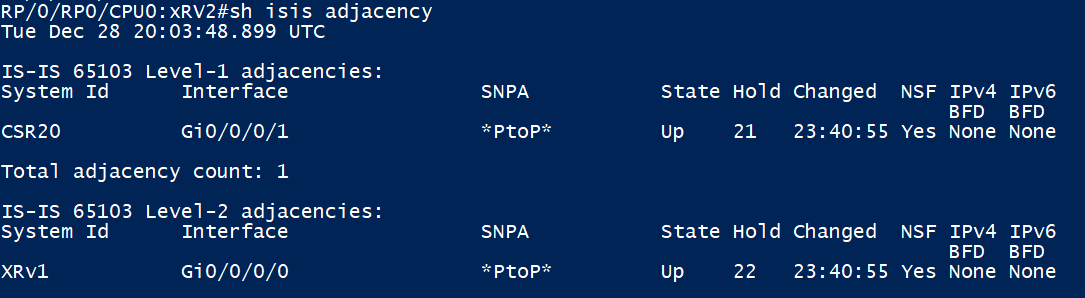
XRv2 has a P2P ISIS-Adjacency up with XRv1

XRv2 is learning the loopback and P2Ps of all devices in our topology
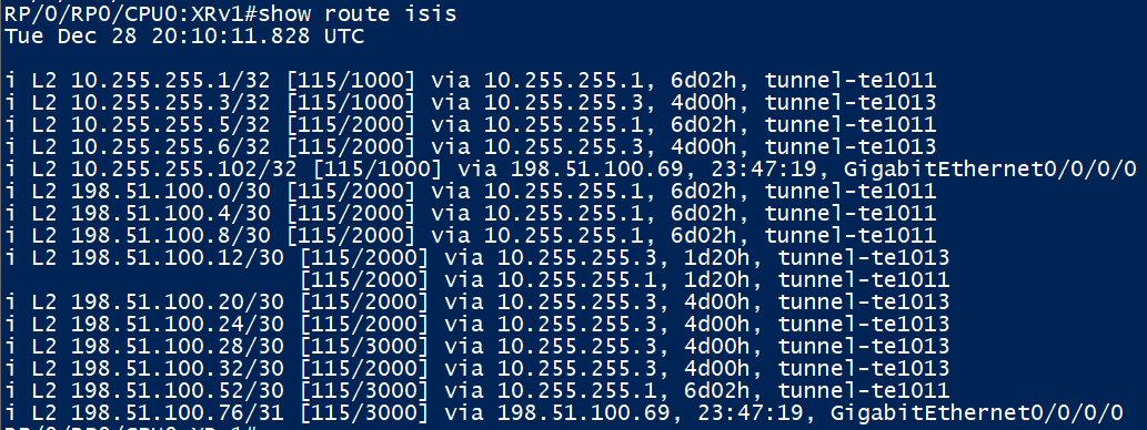
Same with XRv2, but XRv2 will be using it’s RSVP LSPs for forwarding
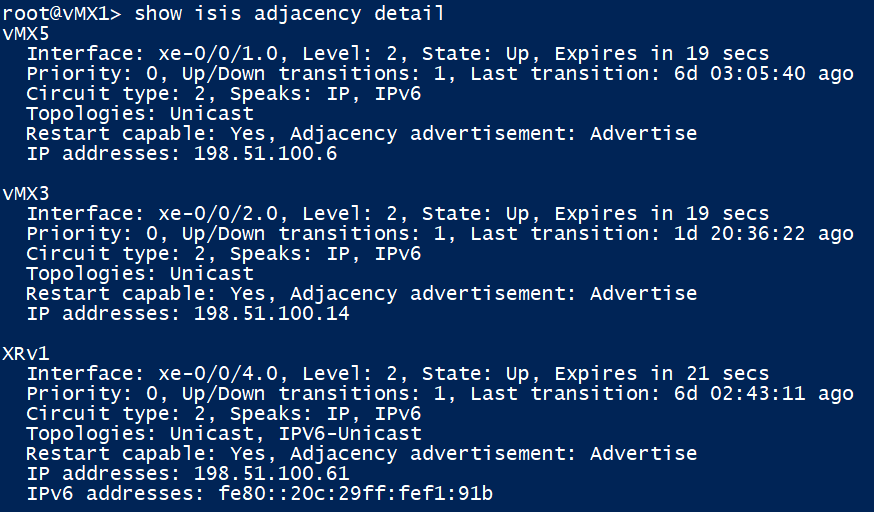
vMX1 has its level 2 adjacencies up with vMX3,5 and XRv1

vMX1 is learning the underlay as expected
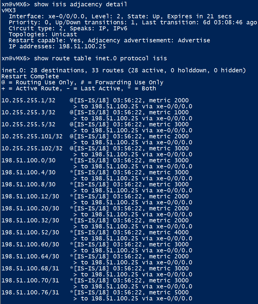
vMX6 is fine too
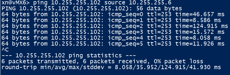
A ping from the loopback of vMX6 to XRv2 is a promising sign that the underlay is working as expected.
PE LDP Verification
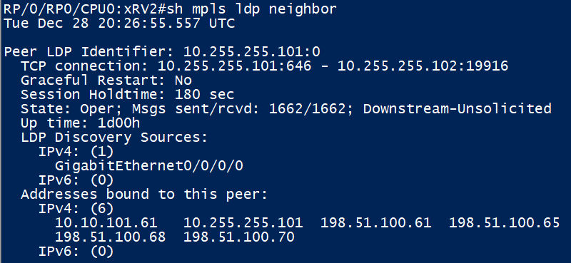
XRv2’s LDP neighbour to XRv1 is up. We can see some of the Addresses that labels are received for.

Here are the Label Bindings we receive from our only LDP peer XRv1. E.g. for traffic going to vMX6 (10.255.255.6), XRv1 expects us to ‘Push’ a outer label of 24005. An implicit null (label 3) is signalled for anything XRv1 is generating a label for, since we are directly connected to it.
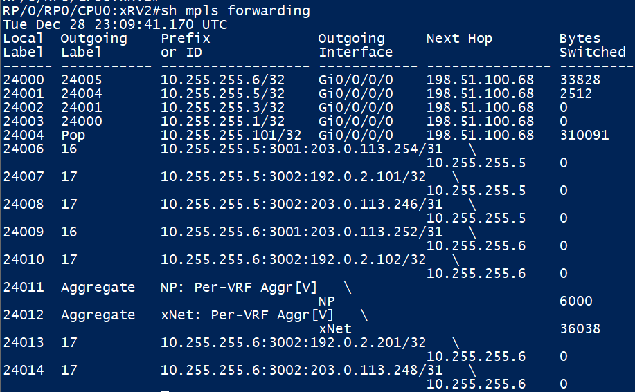
Added a little later, the output above shows how XRv2 handles MPLS (LDP in this case) labels. For traffic to destined to vMX 5 (10.255.255.5), we will impose a ‘outgoing’ label of 24004. This output will be re-visited later
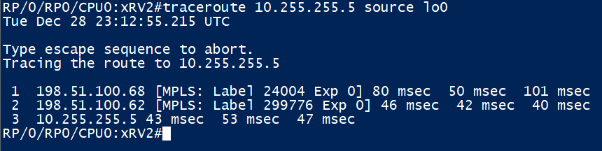
A traceroute to vMX5 verifies the above
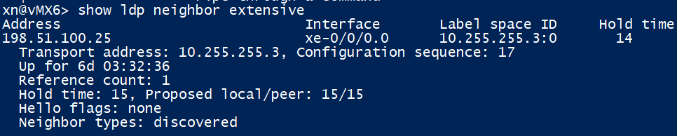
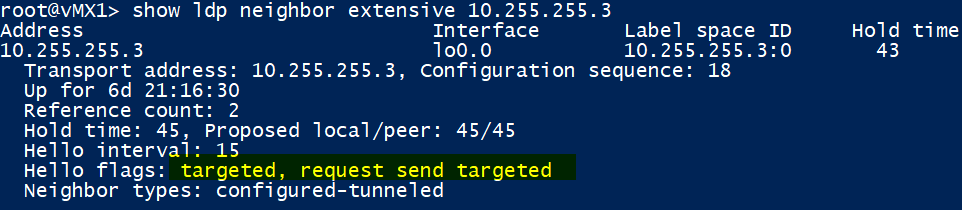
Looking at vMX6, it has its LDP neighbour up to vMX3 too as expected. Note that the transport address for vMX3 is its loopback as it is running LDP on it; that address was preferred. The transport address is the one that the TCP session for which the label exchange will be formed to – after a neighbour has been discovered (via UDP 646). It’s vital we have a route for this to prevent any label issues. The ‘discovered’ flag above also verifies that we learnt the neighbour over a local link on which LDP speaking devices will send hellos

Here are the label bindings received from vMX3 and also sent towards it.
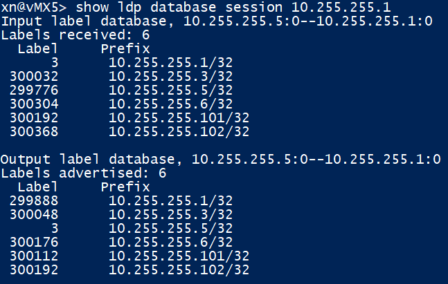
Same as above, but for vMX5 to / from vMX1. Traffic that needs end up at XRv2 (10.255.255.102) should have a outer (transport) label of 300368 imposed as seen below:
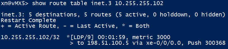
The inet.3 table in Junos is populated with routes created by RSVP or LDP, it is used by BGP to lookup a next-hop first by default; to see if there is a labelled next hop available. We can see that we have a labelled path to XRv2 and need to push label ‘300368’ to send traffic towards it.
Core RSVP LSPs & Targeted LDP Sessions
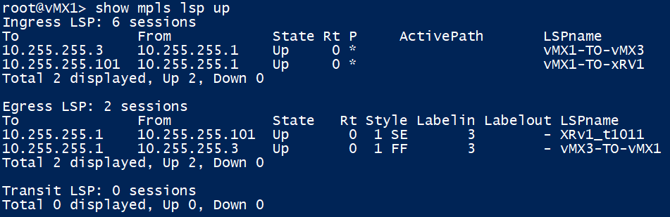
vMX1 has 2 ingress (locally originating) LSPs up, one from vMx3 and the other from XRv1. You can see the LSPs in reverse to this device too. Since all our RSVP egress devices are 1 hop away, the LSP egress will signal label 3 (implicit null) for any traffic going to them.
What this means in our topology currently, is that RSVP labels along with LDP tunnelling won’t get used in the core yet, this will be re-visited later!
Note the ‘show mpls lsp’ session and ‘show rsvp session’ output on junos are identical.

We can see LDP sessions to vMX3 and XRv1 on their loopbacks as being up, along with a ‘normal’ LDP session to our PE ‘vMX5’

Verifying that our targeted LDP session to vMX3 is up

We are receiving LDP label bindings from vMX3
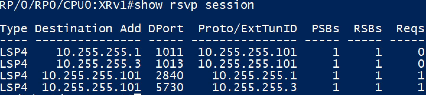
Now onto checking XRv1’s RSVP sessions – note the requests to the bottom 2 destinations, indicating that XRv2 responded with a RSVP Reservation message in response to a RSVP path message.

Looking at the above, we can see that XRv1 has 2 targeted LDP sessions up to vMX1 & 3, along with one to its local PE XRv2

XRv2 is receiving label bindings as expected from its LDP neighbours
BGP (VPNv4) Verification
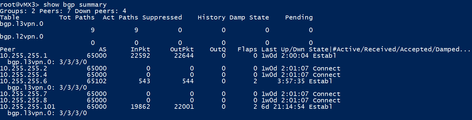
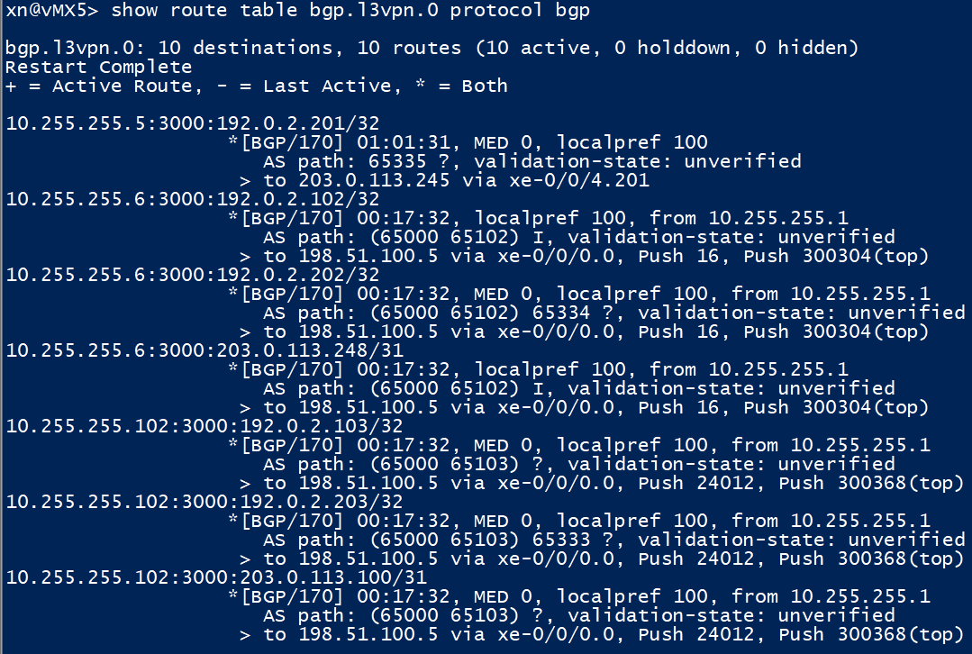
vMX3 (our VPNv4 RR in the core) has its BGP Sessions up to vMX1 and XRv1 in AS65000 and also with vMX6 in AS65102. It is learning 3 VPNv4 routes from each of its peers, which it then stores in the bgp.l3vpn.0. The routes in here will not be imported as we have no routing instances on vMX3, but will instead be re-advertised to the other VPNv4 peers
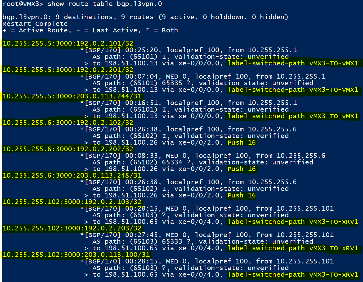
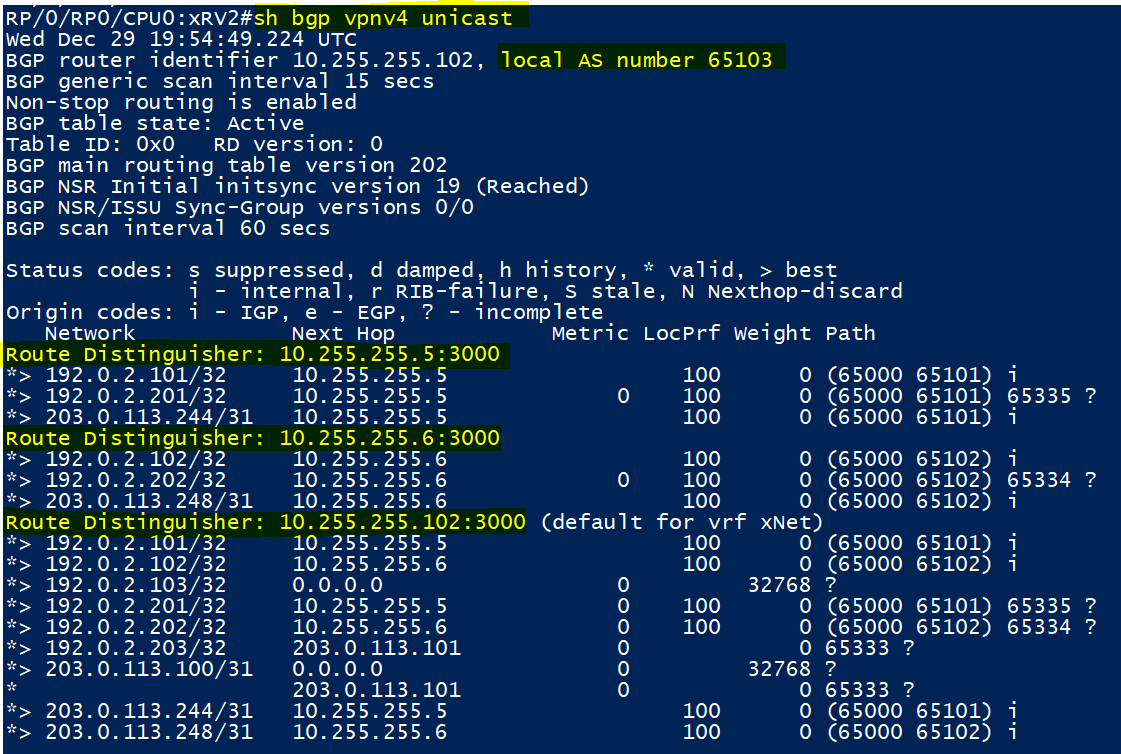
Here are the VPNv4 routes learnt, as you can see they are in the IP:Number formation mentioned earlier in the design overview. We can also see that we will either use a RSVP LSP or a LDP label to reach these next hops.
Notice how all the routes learnt from vMX5 within the xNet VRF request the same ‘inner label’ be pushed, this is what the ‘vrf-table-label‘ command achieves. Without this, the inner label would be assigned per a common next-hop value. More on the inner label below..
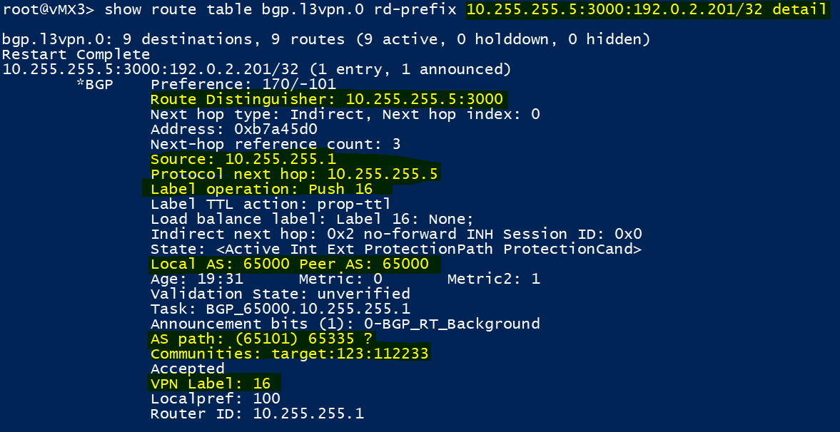
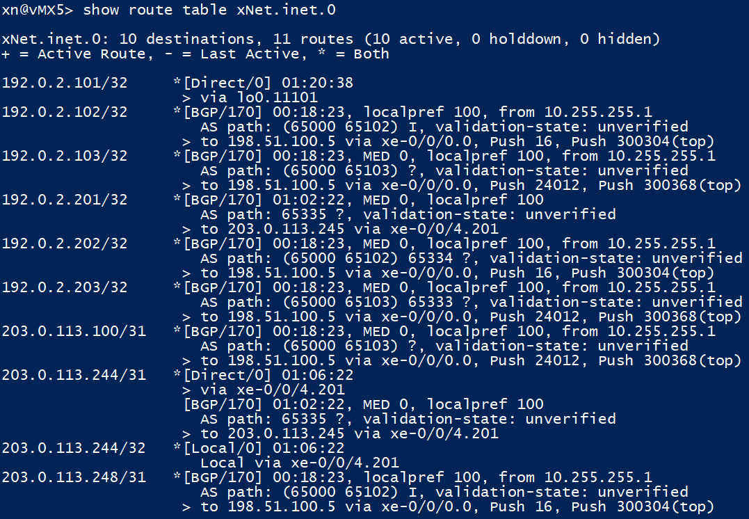
If we look at the 192.0.2.201/32 loopback address that we learn from CPE 101, there are a number of things we can see:
- The route originates in AS 65335, it then transits a intra-confederation AS (note the brackets) AS65101 before being learnt from vMX1 in ‘Peer AS: 65000;’ via IBGP
- It is tagged with a BGP extended community attribute of ‘123:112233,’ which is the route-target we configured on vMX5 within the ‘xNet’ routing instance
- A VPN Label of ’16’ was sent with the update; we will push this as a inner label should we wish to send traffic into the ‘xNet’ VRF on vMX5
- To send traffic to 192.0.2.201/32 in the ‘xNet’ VRF, we are using the BGP next hop of 10.255.255.5
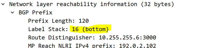
Here is a image showing how the ‘inner / VPN’ label is carried in the VPNv4 update for another prefix in the same VRF – this was captured between vMX3 and vMX1.
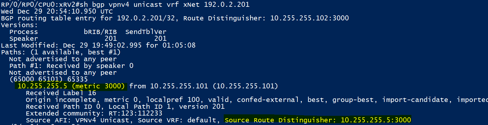
Drilling down into the VPNv4 update for 192.0.2.201/32 on XRv2 AFTER it has been imported into the ‘xNet’ VRF, we can see that the BGP next hop is preserved

XRv2 imports all the VPNv4 routes as seen on the ‘sh bgp vpnv4 unicast’ output earlier above, more specifically on the bottom part of that image
Looking at vMX5, we have no issues here. vMX6 has been tested but isn’t shown as it will add no extra value here.
Connectivity Tests / Traffic Flow
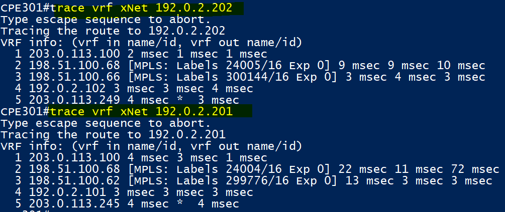
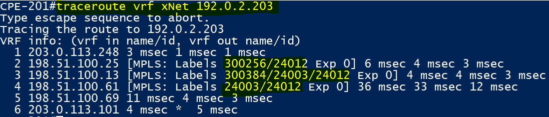
CPE301 has end to end connectivity to CPE101 and CPE 201. Both paths take the IGP shortest paths and are labelled. CPE301 to 201 (192.0.2.202) goes via XRv1 to vMX3
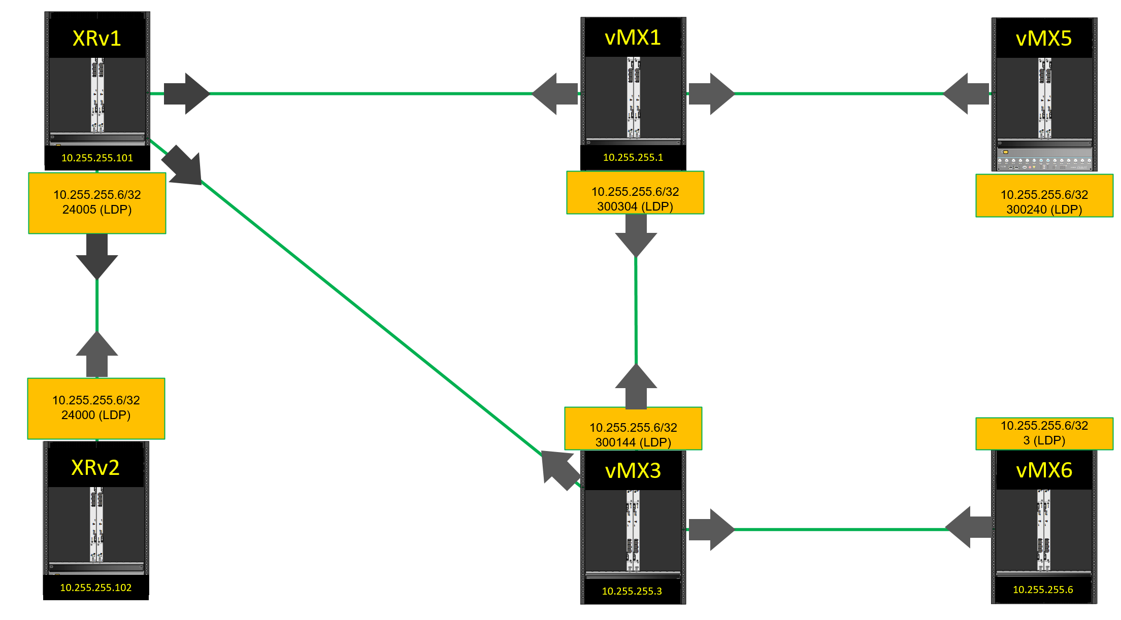
Here is a diagram better illustrating the MPLS labels used between CPE301 (connected to XRv2) and CPE201 connected to vMX6. Note the arrows indicate how each LDP neighbour shares it’s local label mapping for a prefix (FEC). e.g. XRv1 has a local label mapping of ‘24005’ for 10.255.255.6/32 which it shares to all it’s LDP neighbours. Other LDP devices do the same. Since LDP isn’t a routing protocol, XRv2 and vMX5 send label mappings for 10.255.255.6/32, yet it can’t be reached through them.
The traffic flow goes like this:
- CPE 201 uses BGP next hop 203.0.113.100 (XRv2) in the xNet VRF to get to 192.0.2.202/32

- As above, XRv2 checks the VPNv4 table and knows it needs to use BGP Next hop 10.255.255.6 and a inner label of ’16’
- 10.255.255.6 resolves to a underlay (IGP) next hop of 198.51.100.68 (IS-IS)
- The packet is sent with a outer LDP transport label of ‘24005’ as per above diagram and a inner service label of ’16
- At XRv1 the packet is received with a outer label of ‘24005’ and it needs to resolve the next hop 10.255.255.6
- 10.255.255.6 resolves to 10.255.255.3 via a underlay (IGP) next hop of ‘tunnel-te1013,’ which was advertised into IS-IS as a next hop interface using the ‘autoroute-announce’ command earlier
- Tunnel-te1013 is essentially a MPLS LSP which ingresses at XRv1 and egresses at vMX3 (10.255.255.3)
- Since XRv2 has previously learnt a label binding from vMX3 for the 10.255.255.6/32 FEC, it will swap label ‘24005’ for ‘300144’ and send the traffic to MPLS LSP Tunnel egress (10.255.255.3 – vMX3)
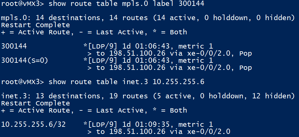
At vMX3, since our next hop 10.255.255.6 is located on vMX6 which is directly connected, vMX6 signals us a ‘implicit null’ (label 3), so we pop the outer (transport) label before forwarding the packet to vMX6 with just the service (inner) label attached
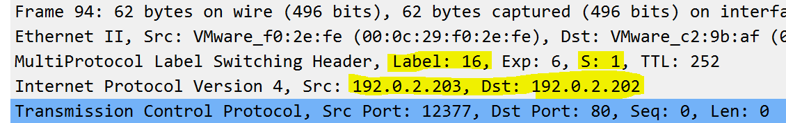
To fully demonstrate our earlier point about popping the transport label, but keeping the inner service label before forwarding to vMX6, see above. Note how the stack pointer is set to 1; indicating the bottom of the stack. This was captured on the link between vMX3 and vMX6.

Once at our final PE vMX6, we can how packets that are received with a label of 16 are forwarded into the ‘xNet’ routing instance. Once in the routing instance and with all labels now removed, we do a IP lookup on 192.0.2.202/32; where it’s then forwarded to CPE201 via 203.0.113.249 (xe-0/0/4.201).
Basic Traffic Engineering & LDP Tunnelling
## vMX3 ##
set protocols mpls path vMX3-vMX1-XRv1 10.255.255.1 strict
set protocols mpls path vMX3-vMX1-XRv1 10.255.255.101 strict
set protocols mpls path vMX3-XRv1 10.255.255.101 loose
delete protocols mpls label-switched-path vMX3-TO-xRV1 no-cspf
set protocols mpls label-switched-path vMX3-TO-xRV1 primary vMX3-vMX1-XRv1
set protocols mpls label-switched-path vMX3-TO-xRV1 secondary vMX3-XRv1

## XRv1 ##
explicit-path name XRv1-vMX1-vMX3
 index 10 next-address strict ipv4 unicast 10.255.255.1
 index 20 next-address strict ipv4 unicast 10.255.255.3
interface tunnel-te1013
 no path-option 1 dynamic
 path-option 5 explicit name XRv1-vMX1-vMX3
 path-option 10 dynamic
If we now apply the above, our previous Path from CPE301 to CPE201 will be forced to go via vMX1 as a extra hop in both directions now. This is as we will now force the MPLS LSP between vMX3 and XRv1 to ignore the IGP shortest path and specify a explicit path to use.
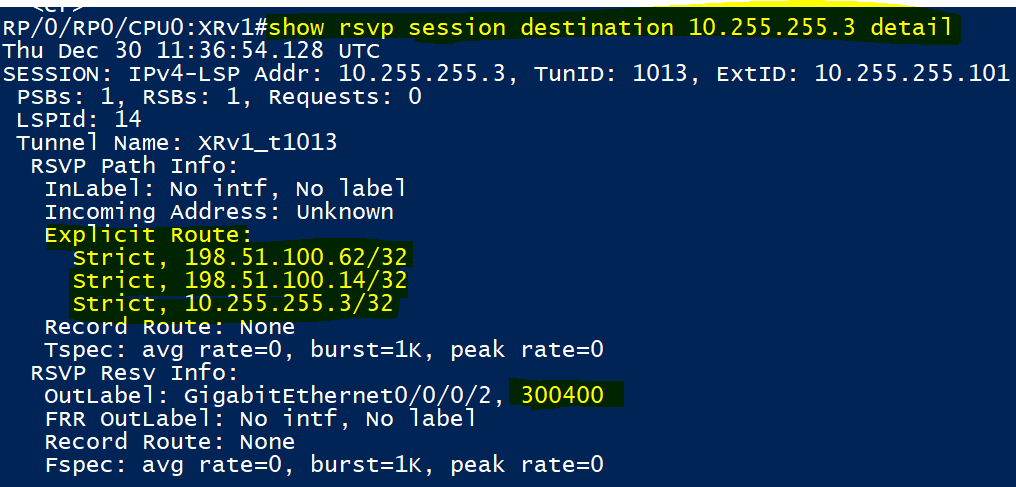
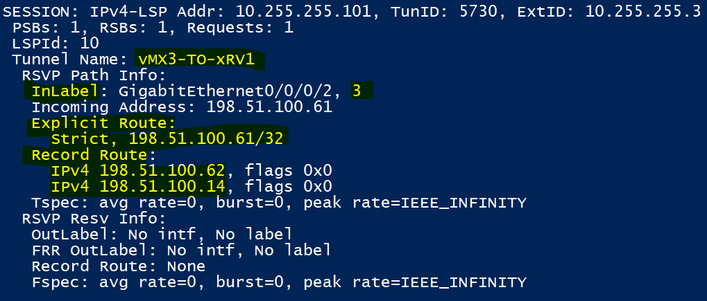
In the above outputs taken from XRv1, we can see the ingress LSP towards vMX3 and the egress one coming in from vMX3. Notice how the ‘strict (explicit) hops’ configured above are shown.

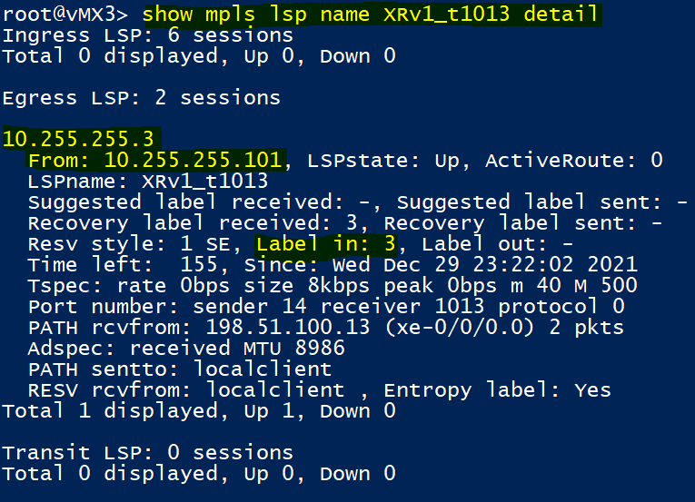
Also in similar outputs taken on vMX3, notice the explicit hops configured in the ‘primary path.’ vMX3 is the headend / egress for the LSP in the 2nd image above, so signals a implicit null.

As you can see above, we have a extra set of outer labels! This is where LDP Tunnelling is taking place. LDP Tunnelling is now possible since our RSVP neighbours XRv1 and vMX3 are forced to send traffic through vMX1 and as such XRv1 or vMX3 now have to impose a RSVP transport label. Previously due to the single hop RSVP LSP, the ingress nodes were signalled a implicit null and couldn’t impose a label as a result.
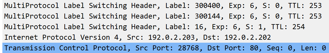
Another packet capture snippet. That’s a few MPLS labels stacked there..
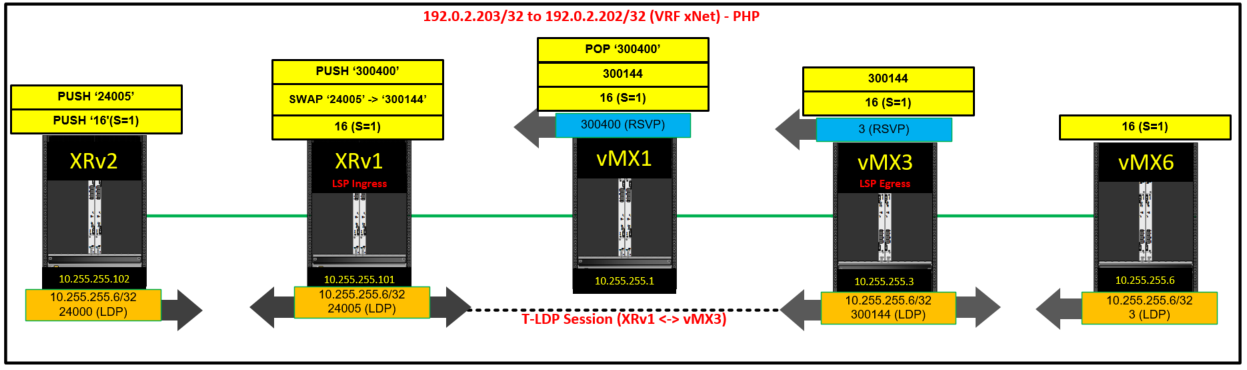
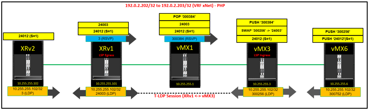
The 2 diagrams above should make LDP Tunnelling and label allocation in general a lot more clear – click for enlarged versions. Note the targeted LDP session between XRv1 and vMX3 for LDP Tunnelling.
Note how RSVP doesn’t allocate a per prefix, unlike LDP. RSVP expects the traffic to come in with the same label, as long as it’s via the same LSP. This is more clearly seen below:
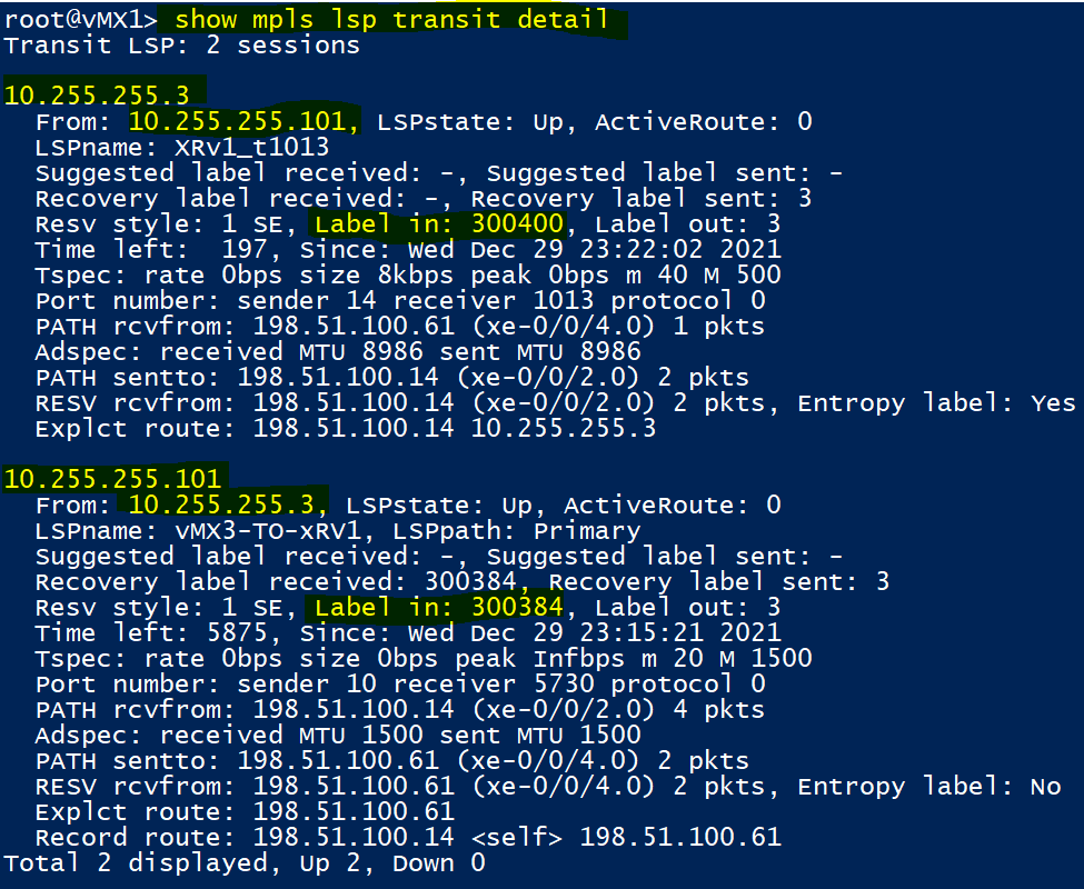
You can see that vMX1 expects traffic coming to it from either VMX3 or XRv1 to use a particular label.